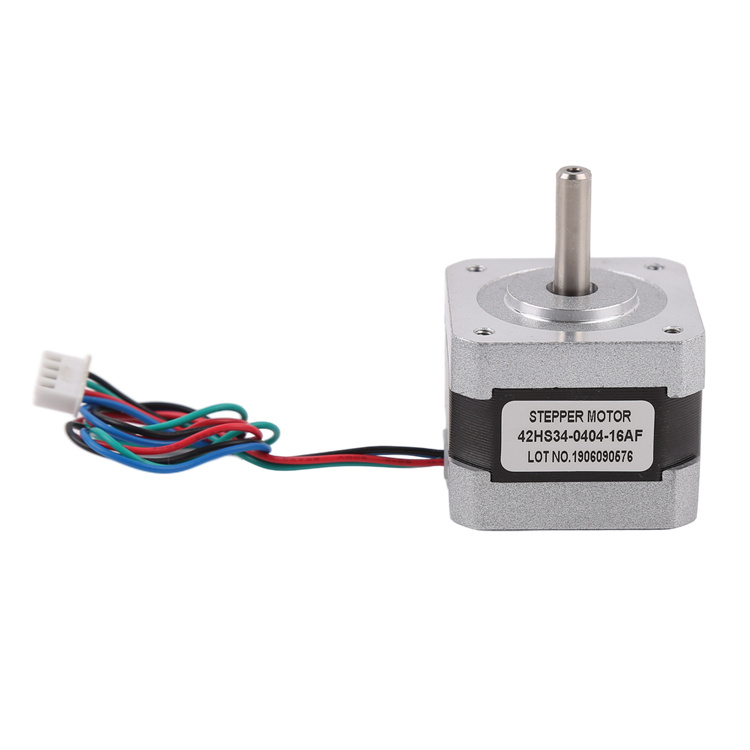
स्टेपर मोटर एक सामान्य प्रकार की मोटर है जो आगे और पीछे घूमने की क्षमता रखती है। तार बदलने का अर्थ है स्टेपर मोटर की गति की दिशा बदलने के लिए उसके पावर कनेक्शन को बदलना। तार बदलने के कई अलग-अलग तरीके हैं, और तार बदलने के एक सामान्य तरीके के बारे में नीचे विस्तार से बताया जाएगा।
स्टेपर मोटर एक विशेष प्रकार की मोटर होती है जो एक निश्चित स्टेपिंग कोण पर घूम सकती है। इसे विद्युत आपूर्ति की ध्रुवता या धारा प्रवाह की दिशा बदलकर आगे और पीछे घुमाया जा सकता है। एक स्टेपर मोटर में आमतौर पर दो या चार कुंडलियाँ होती हैं, जहाँ प्रत्येक कुंडल विद्युत धारा द्वारा संचालित होता है।

तार परिवर्तन विधि का मूल सिद्धांत कुंडलियों में धारा प्रवाह के क्रम को बदलना और कुंडलियों को एक अलग क्रम में सक्रिय करके स्टेपर मोटर की गति की दिशा बदलना है। चार-तार वाले स्टेपर मोटर में तार बदलने की एक सामान्य विधि का नीचे विस्तार से वर्णन किया गया है।
सबसे पहले, स्टेपर मोटर की कुंडलियों के क्रम को समझना ज़रूरी है। स्टेपर मोटर में आमतौर पर दो आसन्न कुंडलियाँ होती हैं, जिनमें से प्रत्येक में एक टर्मिनल होता है। चार-तार वाली स्टेपर मोटर में, दो कुंडलियाँ होती हैं, जिन्हें कुंडल "A" और कुंडल "B" कहा जाता है। प्रत्येक कुंडल में "A1", "A2" और "B1", "B2" नामक दो टर्मिनल होते हैं। मोटर को चालू करने के लिए इन टर्मिनलों को बिजली की आपूर्ति से जोड़ा जाएगा।
तारों को स्विच करने की इस विधि में, हम स्टेपर मोटर को चलाने के लिए "Vcc" और "Gnd" लेबल वाले दो बिजली के तारों का उपयोग करेंगे। स्टेपर मोटरों को आमतौर पर बिजली कनेक्शन को नियंत्रित करने के लिए एक नियंत्रक (जैसे ड्राइवर या माइक्रोकंट्रोलर) की आवश्यकता होती है।
चरण 1: "A1" को "Vcc" से और "A2" को "B1" से कनेक्ट करें। इस स्थिति में, बिजली आपूर्ति लाइन इस प्रकार होगी: "Vcc" - "A1" - "A2" - "B1" - "Gnd". -Gnd"।
चरण 2: "B2" को "Vcc" से कनेक्ट करें और "A1" को डिस्कनेक्ट करें। इस बिंदु पर, बिजली आपूर्ति कनेक्शन इस प्रकार होगा: "Vcc" - "B2" - "A2" - "B1" - "Gnd". -Gnd"।
चरण 3: "A2" को "Vcc" से कनेक्ट करें और "B1" को डिस्कनेक्ट करें। इस बिंदु पर, बिजली आपूर्ति कनेक्शन इस प्रकार होगा: "Vcc" - "B2" - "A2" - "Gnd"।
चरण 4: "B2" को डिस्कनेक्ट करें और "A2" और "A1" को फिर से कनेक्ट करें। इस बिंदु पर, बिजली आपूर्ति लाइनें इस प्रकार हैं: "Vcc" - "A1" - "Gnd"।
उपरोक्त चरणों के अनुसार पावर केबल को जोड़कर, स्टेपर मोटर को आगे और पीछे घुमाया जा सकता है। सबसे पहले, यह सुनिश्चित करना आवश्यक है कि पावर कॉर्ड सही ढंग से जुड़ा हो ताकि शॉर्ट सर्किट और मोटर सर्किट को होने वाली अन्य क्षति से बचा जा सके। यह भी सुनिश्चित करना आवश्यक है कि पावर कॉर्ड स्टेपर मोटर को चलाने के लिए पर्याप्त धारा प्रदान कर सके।
यह ध्यान रखना ज़रूरी है कि स्टेपर मोटर के लिए तार बदलने की विधि विशिष्ट मोटर मॉडल और निर्माता के आधार पर भिन्न हो सकती है। इसलिए, स्टेपर मोटर चलाते समय, यह सुनिश्चित करने के लिए कि तार बदलने की सही विधि का उपयोग किया जा रहा है, मोटर के तकनीकी मैनुअल या निर्माता के निर्देशों को देखने की सलाह दी जाती है।
संक्षेप में, स्टेपर मोटर तार परिवर्तन विधि, कुंडलियों से धारा संयोजन के क्रम को बदलकर मोटर को आगे और पीछे घुमाने की एक विधि है। पावर केबलों को अलग-अलग तरीकों से जोड़कर, स्टेपर मोटर कॉइल्स के सक्रिय होने के क्रम को बदला जा सकता है, जिससे मोटर की गति की दिशा बदल जाती है। स्टेपर मोटर तार परिवर्तन प्रक्रिया करते समय, मोटर के तकनीकी मैनुअल या निर्माता के निर्देशों को ध्यानपूर्वक पढ़ना और यह सुनिश्चित करना आवश्यक है कि पावर केबल ठीक से जुड़े हुए हैं और पर्याप्त धारा प्रवाहित हो रही है।
पोस्ट करने का समय: 24 जून 2024
